Basics of LCMS Systematic Troubleshooting
LCMS Troubleshooting Course
1 - Basics of LCMS Systematic Troubleshooting
2 - Preventive Maintenance Measures
3 - Pressure Issues
4 - No Peaks Detected
5 - Changes in Peak Shape - Part 1
6 - Changes in Peak Shape - Part 2
7 - Ghost Peaks
8 - Peak Area Fluctuations
9 - Baseline Disturbances
10 - Retention Time Fluctuations - Part 1
11 - Retention Time Fluctuations - Part 2
12 - Changes in Chromatographic Resolution
13 - Changes in MS Response
14 - Undesired Fragmentation & Ion Source Settings
15 - Course Summary & Quiz
Welcome!
Welcome to our Free Online Course: Troubleshooting in Liquid Chromatography Mass Spectrometry!
We are excited to have you join us for this seven-week journey into the world of troubleshooting and preventing common errors in LCMS applications. Each week, you will receive an email with two or three informative topics designed to enhance your understanding and skills in mass spectrometry troubleshooting.
Our first week will establish the foundations of systematic troubleshooting, providing you with valuable general guidelines for preventing and avoiding common errors. It will also look at the basics of the mass spectrometer components.
Basics of Systematic Troubleshooting
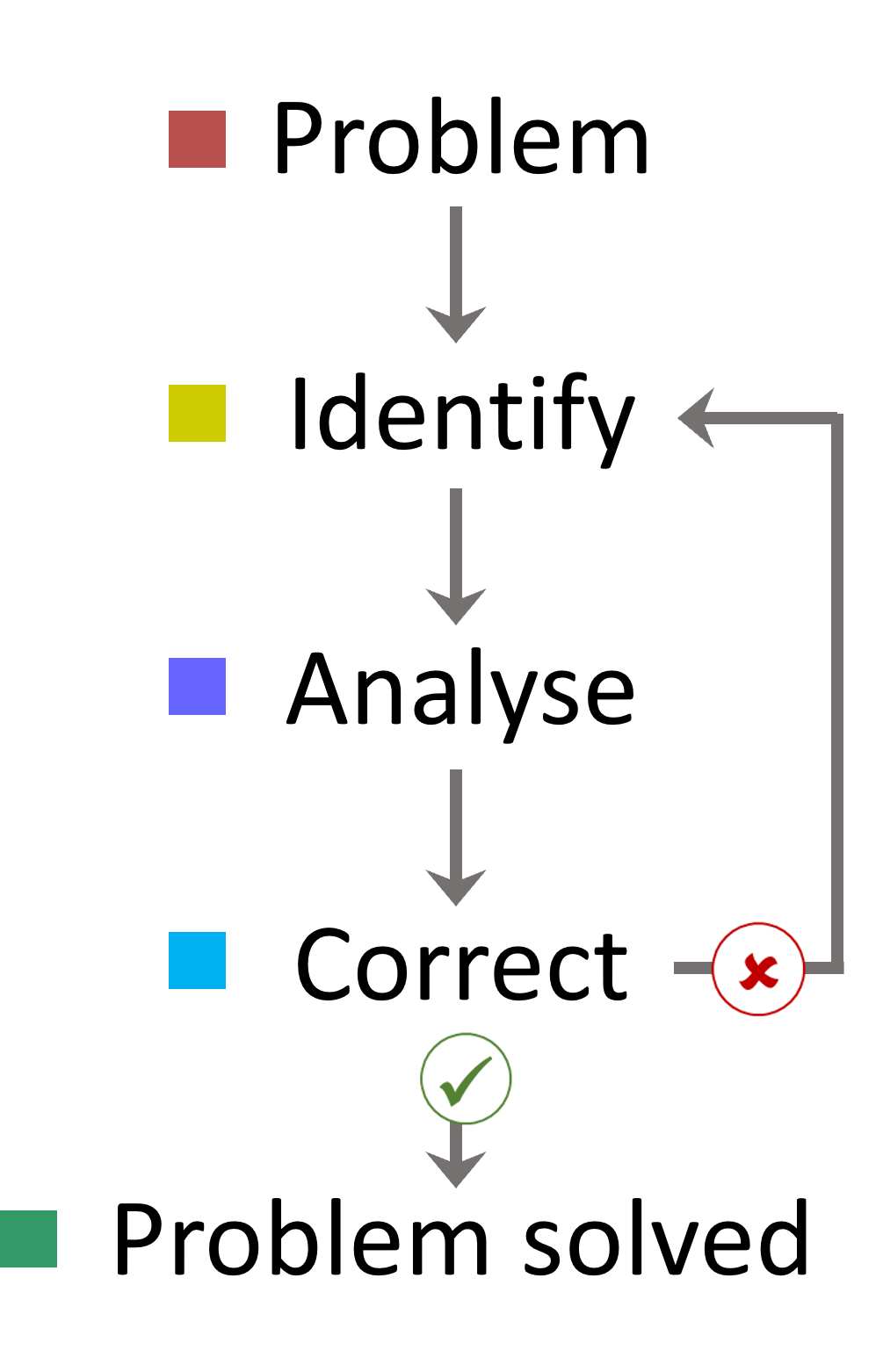
A systematic approach is crucial for effective troubleshooting and problem resolution. By approaching issues in a stepwise fashion, we can begin to understand the problem:
1. Narrow Down the Problem
- Focus on one potential issue at a time. This allows you to identify the cause more accurately.
2. Understand Your System
- Familiarise yourself with your LCMS and method / application. Key aspects to monitor include:
- Baseline of a blank measurement
- Pressure behaviour
- Retention time and peak area of analytes
- Peak shapes
- Tuning Results
Having consistency between runs - such as a standard you run with each batch or buying pre-mixed solvents - can help you track these parameters effectively.
3. Analyse and Resolve
- After identifying a problem, it's possible to understand and narrow down potential errors. In upcoming course topics, we will cover the most common issues and the changes that can be made to resolve the issue. If a change doesn't solve the problem, start from the beginning and test the next possible source of error. It is important to systematically change only one factor at a time to establish the cause of an error.
4. Document Your Findings
- Keep a record of the errors encountered and the changes made. This documentation benefits you and your colleagues by improving collective knowledge and speeding up future troubleshooting.
5. Dispose of Defective Parts
- When replacing aged components, if the issue has been resolved, dispose of the old / worn parts immediately to avoid reinstalling them later. If the replaced part hasn’t solved the issue then it could be worth keeping them for a later date. Keep them somewhere safe and labelled so colleagues know what they are.
Some of the most common sources of error which should be investigated first include:
- Electrical connections and power supply
- Communication between the instrument and the PC
- Standards and sample preparation
- Mobile phase preparation
- The analytical method conditions
- LC fittings, connections and flowpath
- Needle rinse and seal washes
- LC pump pressure and potential air bubbles
- Ion source maintenance and cleaning
- MS vacuum
- External generators and cylinder issues including Argon gas (level and pressure), gas generator (pressure readings) and roughing pump issues (oil level and gas ballast)
Only one variable should be changed at a time to logically identify trends and isolate possible causes. Everything should be documented, including retention times, normal LC pressure and samples injected. A system suitability test can provide vital performance information to assist with troubleshooting.
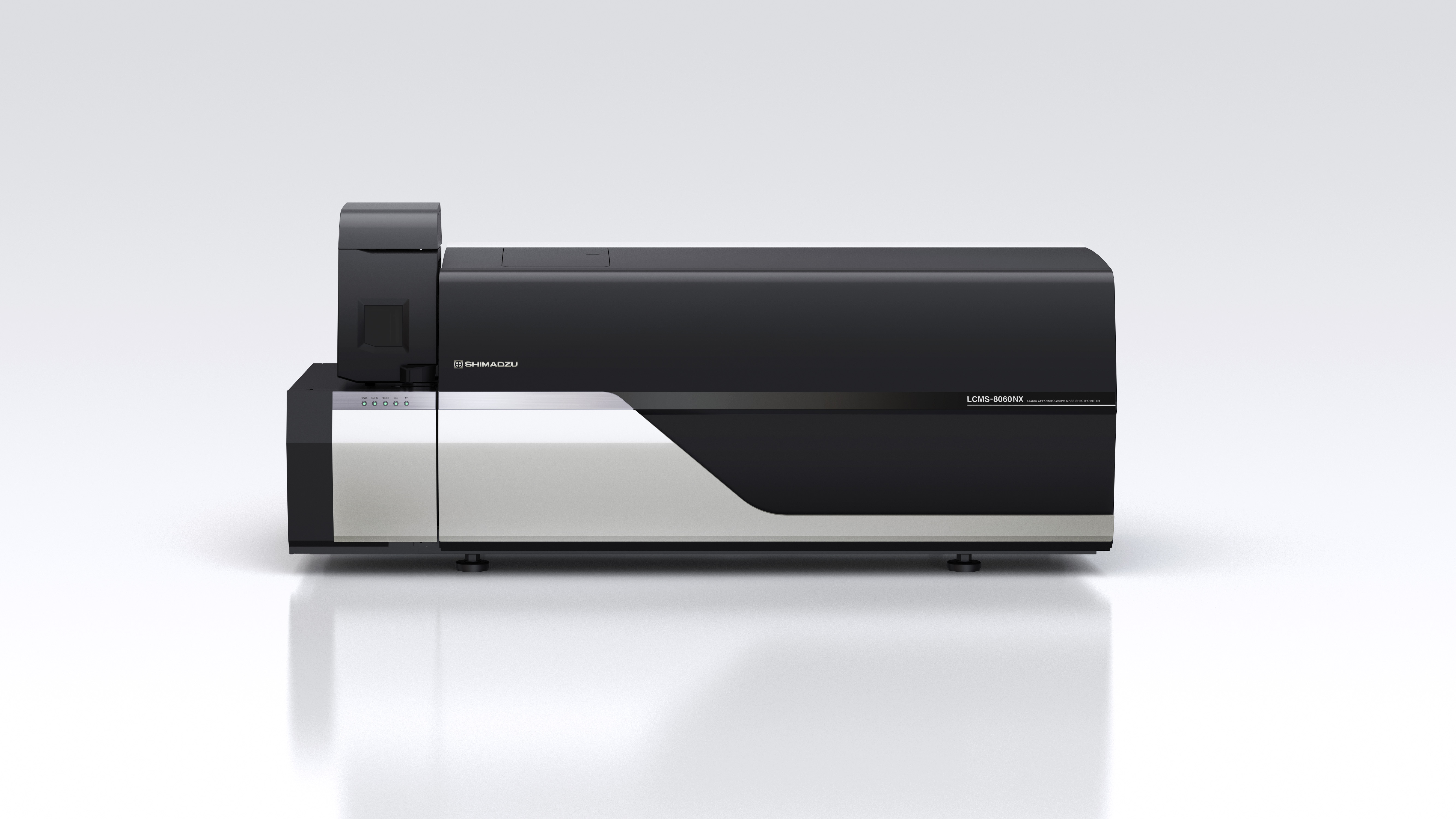
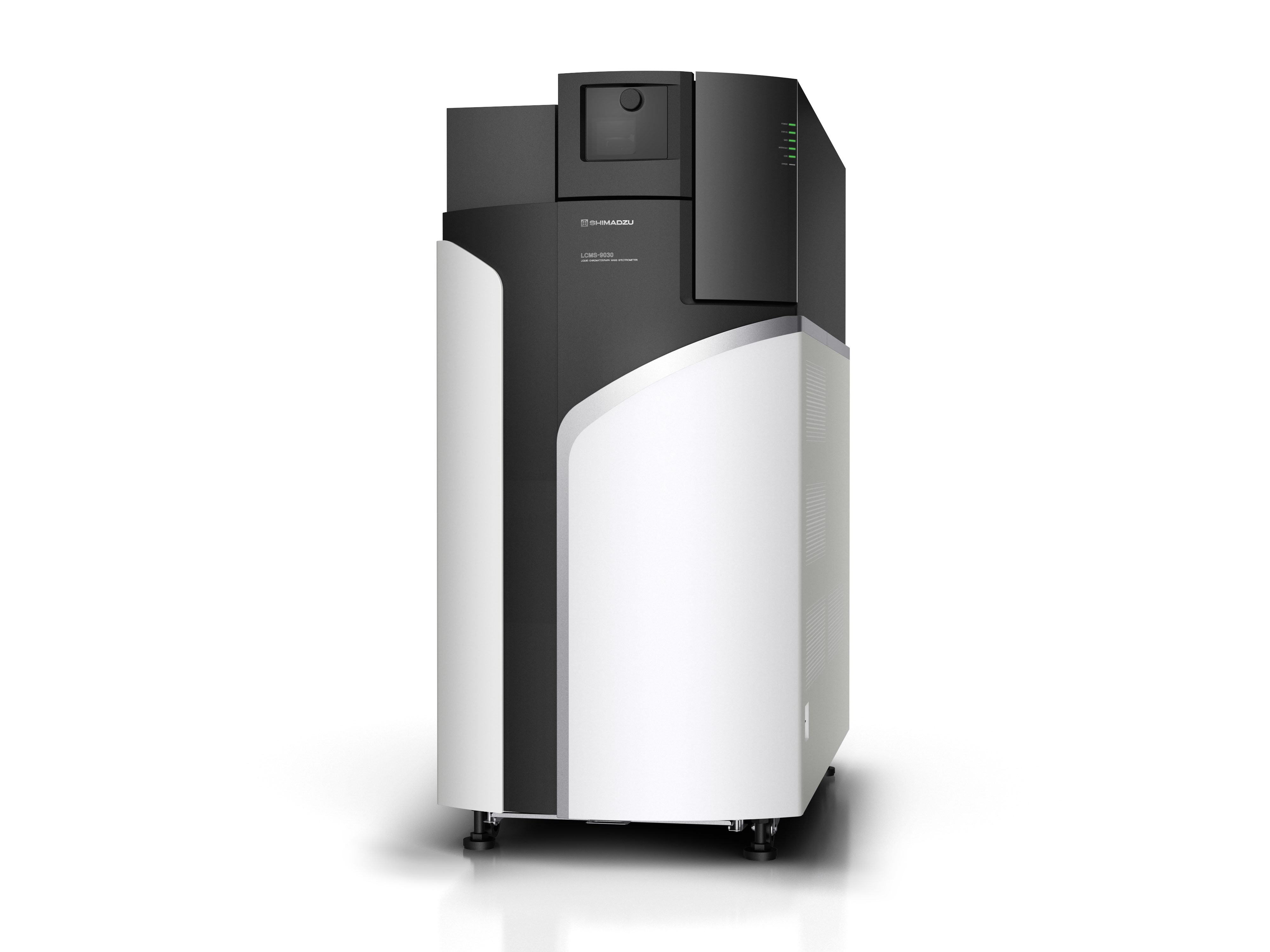
Structure of an LCMS
To be able to fully troubleshoot, we first need to understand the structure of a typical LCMS system. An LCMS is composed of two instruments – the liquid chromatograph system and the mass spectrometer.
Every HPLC is fundamentally built the same. It consists of a solvent delivery system, an injector, a separation column, a detector, and the solvent waste. Ideally, an online degasser and a column oven are installed to ensure reproducibility. These modules are covered in the HPLC Troubleshooting Course, which we encourage you to look through to learn how to eliminate common issues with the LC.
The mass spectrometer is composed of three components:
1. Ion Source

- Responsible for ionising and transferring analytes into the gas phase
2. Analyser
- The core of the mass spectrometer, which separates ions based on their mass-to charge ratio (m/z)
3. Detector
- Captures the ions, amplifies the signals and transmits the data to a workstation for recording and analysis
Let's investigate each component in more detail:
Ion Sources:
A variety of ionisation technologies are available which should be selected based on the properties of the analytes to be analysed. Key factors include polarity range, molecular size of analytes and sample complexity. Figure 1 gives an overview of typical ionisation techniques based on the polarity and molecular weight of the compounds. The most ubiquitously used technique is the electrospray ionisation (ESI) mode. Below we will examine the two most commonly used techniques.
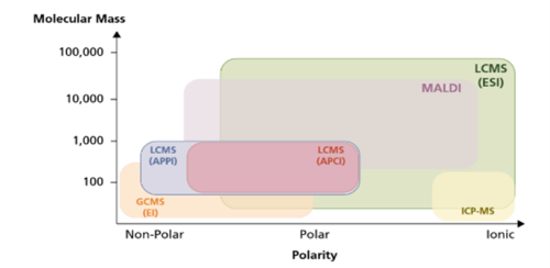
Fig. 1 Overview of common ionisation techniques and areas of application
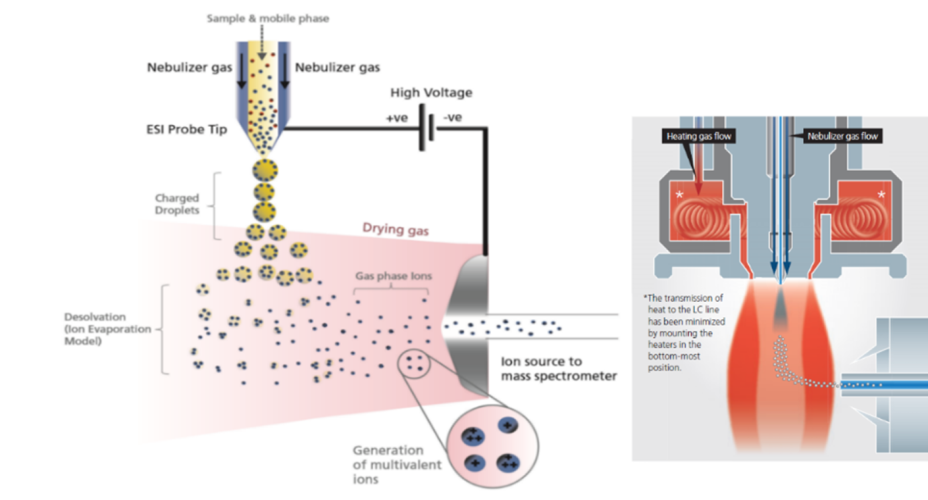
Fig. 2 Process of electrospray ionisation (left); schematic structure of a heated ESI source (right)
In electrospray ionisation, a fine mist of the sample solution (introduced via HPLC or a syringe pump) is generated at the tip of the ESI capillary. A high voltage (3–5 kV) applied to the ESI capillary induces charge accumulation on the droplet surface. To assist solvent evaporation, a nebulising gas is introduced parallel to the ESI spray. Often, an additional heating gas is used to enhance evaporation and ionisation. As the solvent evaporates, the droplet size reduces, concentrating the charges until a Coulomb explosion occurs, transferring charges to individual analytes. This process repeats until only ions remain in the gas phase. ESI is a "soft" ionisation method, causing minimal or no molecular fragmentation in the source.
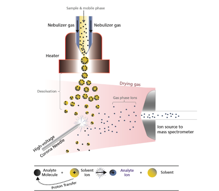
Fig. 3 Process of the APCI source
The APCI source resembles the ESI source. It is primarily used for smaller, less or moderately polar analytes. In APCI, the solvent and sample solution are vaporised using high temperatures and auxiliary gases like nitrogen. The corona needle ionises gas and solvent molecules, transferring charges to analyte molecules through radical reactions. Unlike ESI, APCI mostly produces singly charged ions due to the greater molecular spacing in the gas mixture.
Analysers:
The mass analyser is one of the critical parts of the instrument which separates the ions. There are several types of mass analyser which all have different principles and mechanisms. Below are some of the most commonly employed.
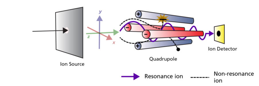
Fig.4 Representation of quadrupole technology
A quadrupole consists of four parallel cylindrical metal rods (Fig. 4). Both direct current and high-frequency alternating voltage (radiofrequency) are applied to the rods. The alternating voltage polarity is identical for opposing rods. Depending on the tuning of the voltages, ions with specific m/z values pass through the quadrupole, while others are filtered out due to unstable resonances. The stability of ion motion in the quadrupole is described by the Mathieu equation, below. Only ions with stable oscillations pass through the quadrupole to the detector. By rapidly changing voltage settings or ramping them, the quadrupole can selectively filter ions or analyze specific mass ranges.
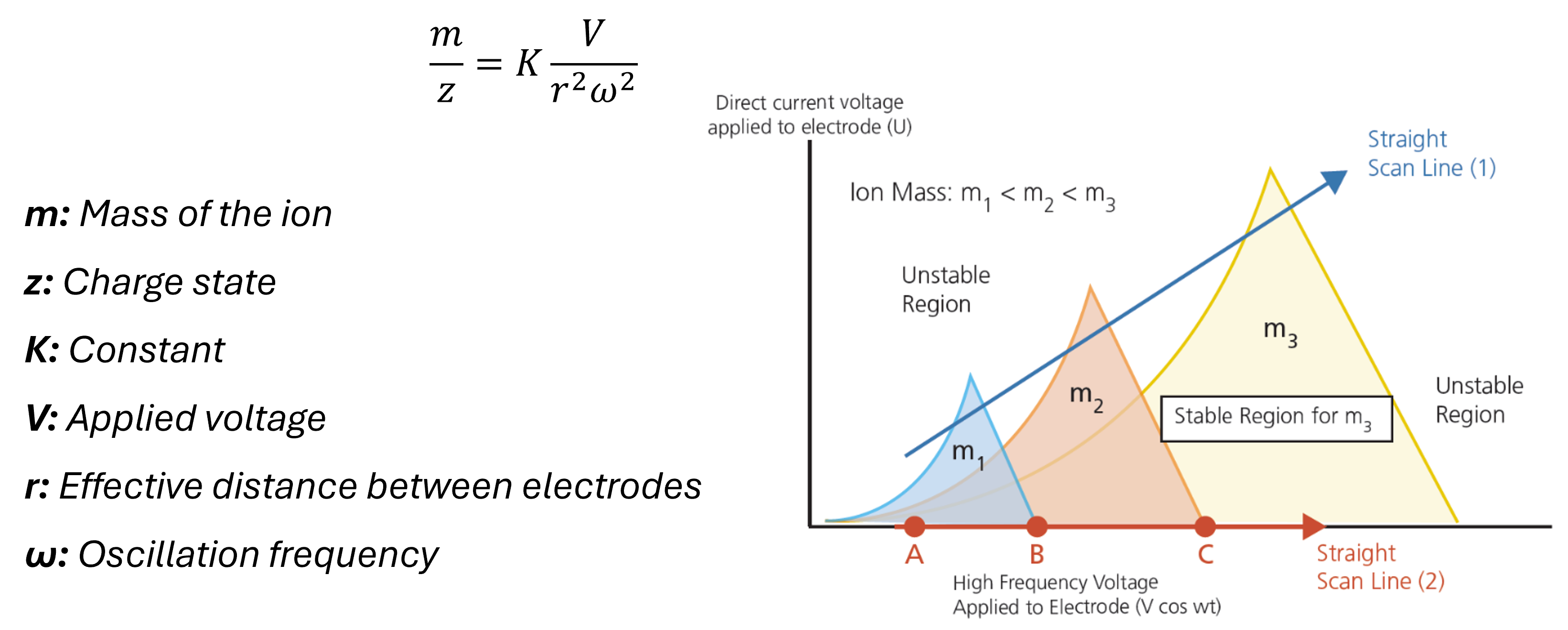
Fig. 5 Graphic of the stable fields in the quadrupole
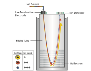
Fig. 6 Schematic representation of a TOF Mass Spectrometer
In TOF-MS, ions are directed into a field-free flight tube. They are separated based on their flight times, which depend on their mass-to-charge ratio (m/z).
After ionisation, ions are pre-selected and focused using ion optics. They are then accelerated by high voltage into a field-free drift region. Smaller m/z ions reach the detector faster than larger ones. TOF-MS generates high-resolution spectra with precise mass accuracy and allows for a wide mass range analysis. However, stable temperature control is crucial, as minor flight path variations can affect mass accuracy.
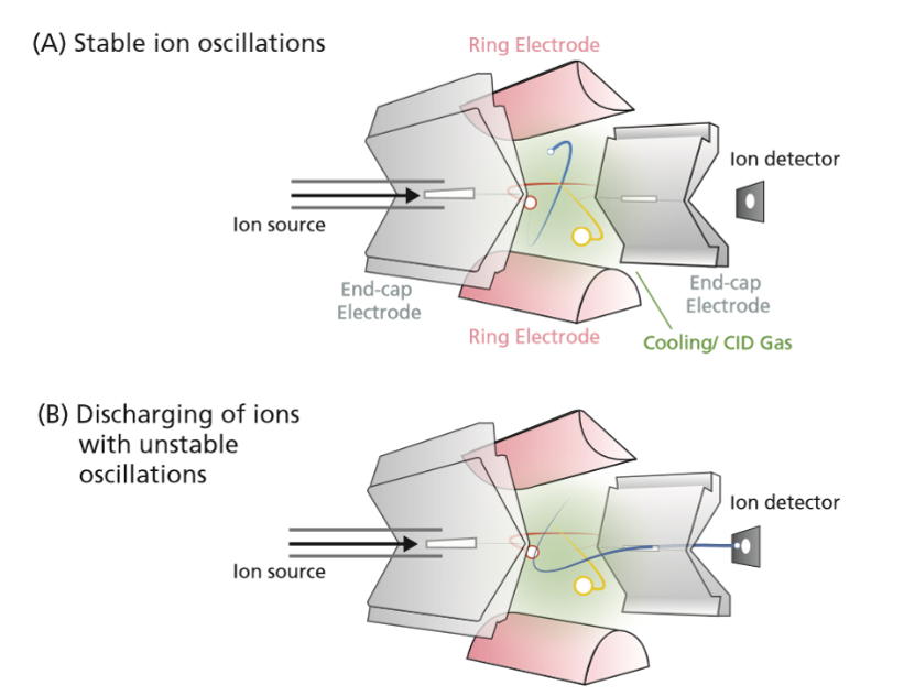
Fig. 7 Structure and principle of the 3-dimensional ion trap
Ion traps come in various designs, such as 2D linear or 3D ring-shaped configurations. Similar to quadrupole technology, ion traps operate based on the Mathieu equation.
To capture ions, end-cap and ring electrodes are grounded, and ions are pulsed into the trap. High-frequency alternating voltage centralises the ions, trapping them. Ions are released by reducing alternating voltage and applying direct current to the end-cap electrodes. Specific m/z ions can be isolated by tuning alternating voltage. Ion traps also enable fragmentation of selected m/z ions using collision gas, allowing detailed MSn analyses for structural determination of unknown compounds.
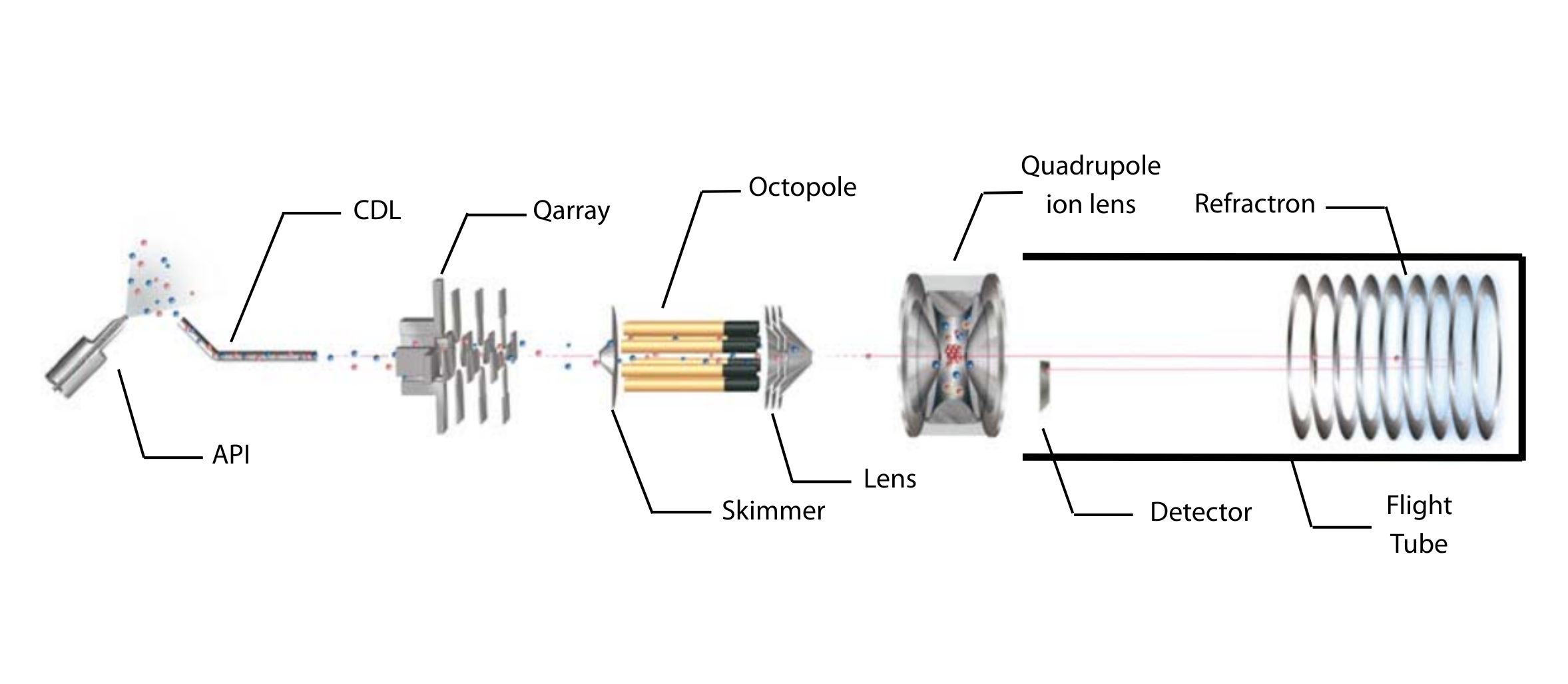
Fig. 8 Instrumentation of an Ion Trap Time-of-Flight (IT-TOF) MS.
Detectors:
Commonly used detectors in mass spectrometry include secondary electron multipliers and microchannel plates (MCP).
Secondary Electron Multiplier
Fig. 9 Schematic of an MS detector
Ions strike a conversion dynode, releasing electrons that are amplified into measurable signals (Figure 9). The ions are bombarded onto the conversion dynode to release a few electrons that are bombarded onto an alternating line of dynodes to increase the detection signal. These signals are displayed on the computer software.
In the next course unit, we’ll explore preventive measures for extending the lifespan of your LCMS and reducing potential problems.
Your Shimadzu LCMS Team
Related Resources
-
-
Watch short videos explaining analytical intelligence features of Shimadzu HPLC systems
-