Split Peaks
GC Troubleshooting Course
10 - Split Peaks
11 - Response Variability
12 - Retention Time Variability
13 - Course Summary & Test
Split Peaks
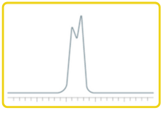
In an ideal chromatogram, peaks should be symmetrical and well-resolved. Split peaks are where a single compound appears as two or more peaks close together and usually indicate problems with sample introduction or vaporisation.
Common Causes and Fixes
1. Manual Injection Issues
The most common cause of split peaks is poor manual injection technique:
- If the syringe plunger is not depressed in one smooth, rapid motion, inconsistent vaporization can occur.
- This results in multiple “packets” of analyte entering the column at slightly different times.
Solution:
- Use an autosampler whenever possible for better reproducibility.
- If injecting manually, ensure smooth, quick, and consistent operation — and regularly clean the syringe to prevent the plunger meeting resistance or sticking.
2. Solvent and Polarity Mismatch
The solvent used for sample preparation or syringe rinsing must be compatible with the column’s stationary phase:
- Mismatched solvent polarity can impair analyte focusing on the column head, leading to peak distortion or splitting.
Solution:
- Apply the principle “like dissolves like.”
- Choose a solvent with similar polarity to the stationary phase or adjust the stationary phase to match your analytes’ properties.
3. Incomplete Sample Vaporisation
If the inlet temperature is too low, analytes may not vaporize fully, resulting in poor transfer and split peaks.
Solution:
- Set an appropriate inlet temperature based on analyte volatility: For most applications: 250°C is a good starting point; for semi-volatiles: increase to 300°C or higher as needed.
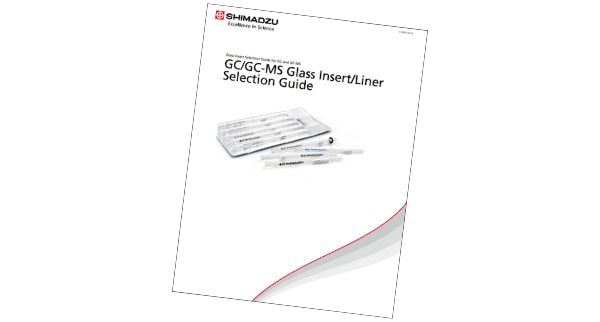
4. Liner Design and Injection Speed
The inlet liner plays a critical role in vaporisation and sample mixing:
- Glass wool increases surface area for vaporization and improves analyte dispersion.
- A baffled or packed liner helps avoid channelling and promotes efficient vapor distribution.
Injection speed also matters:
- Too fast: overwhelms the liner and leads to uneven sample transfer.
- Too slow: may lead to tailing or broader peaks.
Solution:
- Use liners with glass wool or baffled designs for improved vaporisation.
- Adjust injection speed to balance delivery and vaporization — especially with open liners.
5. Overloading or Detector Saturation:
Introducing too much sample can exceed the column or detector’s capacity, particularly in GC-MS systems. In MS, detector saturation can distort peak shape, sometimes mimicking a split peak.
Solution:
- Dilute the sample.
- Reduce the injection volume.
- Increase the split ratio.
- In GC-MS, consider setting the quadrupole resolution to “high” (in MRM mode), which reduces ion flux to the detector.
Summary Tips
| Cause | Fix |
|---|---|
| Poor manual injection | Use autosampler or inject smoothly |
| Solvent polarity mismatch | Match solvent to stationary phase |
| Low inlet temperature | Increase to optimise vaporisation |
| Poor liner design | Use baffled or glass wool liners |
| Fast injection speed | Slow down to improve transfer |
| Sample overload | Dilute, reduce volume, or increase split |
| Detector saturation (MS) | Lower sample load or increase resolution |
Related Resources