No Peaks Detected
LCMS Troubleshooting Course
1 - Basics of LCMS Systematic Troubleshooting
2 - Preventive Maintenance Measures
4 - No Peaks Detected
5 - Changes in Peak Shape - Part 1
6 - Changes in Peak Shape - Part 2
7 - Ghost Peaks
8 - Peak Area Fluctuations
9 - Baseline Disturbances
10 - Retention Time Fluctuations - Part 1
11 - Retention Time Fluctuations - Part 2
12 - Changes in Chromatographic Resolution
13 - Changes in MS Response
14 - Undesired Fragmentation & Ion Source Settings
15 - Course Summary & Quiz
Welcome Back to Unit 4!

Welcome back for another session on LCMS troubleshooting. In previous units, we provided a basic understanding of the different types of MS detectors and when you would use a certain type, typical preventive measures to prevent issues from arising in the first place and the most common causes of pressure issues. This week we will be exploring the causes and solutions when we don’t observe any peak.
It can be extremely frustrating to set a batch running to come back to no usable results. As such, it is always good practice to check the first injection to make sure that everything is working correctly.
If we observe no peaks in our results, we must explore the sample, the LC and the detector as potential causes.
1. MS Setting Issues
| Issue | Description | Solution |
|---|---|---|
| Unsuitable MS Technique for Analyte | The mass spectrometry may not be a suitable detection technique for the physicochemical properties of the analyte (e.g. non-ionisable or thermally unstable compounds). |
Verify the analyte is ionisable under the current ionisation mode (ESI, APCI etc)
Consider an alternative ionisation source or detector if necessary
|
| Incorrect Probe or Capillary Position | Improper probe distance from the orifice or incorrect capillary protrusion can result in inefficient ionisation or poor spray |
Set probe distance to approximately 2-3 mm from the orifice
Ensure the capillary protrudes 0.5-1 mm from the probe
Visually inspect for a stable, uniform spray
|
| Incorrect MS Parameter Settings | Incorrect ion source type, acquisition mode or polarity can prevent analyte ionisation and detection |
Confirm correct ion source, polarity and acquisition mode are selected for target compounds
Check ion source temperature and gas flows are correct and stable
Verify collision gas pressure is set appropriately and is stable
|
| Schedule Acquisition Window Too Narrow | If operating in scheduled MRM or similar modes, the analyte may elute outside the defined event window |
Acquire data across the full run time to verify analyte retention
Adjust retention time window accordingly
|
| Instrument Tune or Performance Drift | Poor MS tuning or detector instability can lead to loss of sensitivity or no peak detection |
Perform a full MS tune and verify acceptable performance
Check calibration standards to confirm mass accuracy and response
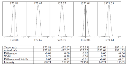
Fig. 1 Example of a tuning file |
| Adduct Formation or Matrix Suppression | Adducts (Na+, K+, NH4+, etc) or matrix effects can suppress analyte signal. |
Inspect spectra for adducts and adjust mobile phase or sample preparation
Use clean glassware and freshly prepared mobile phases
Consider different LC methods or enhanced sample preparation to reduce ion suppression
|
| Sample Below Detection Limits | The analyte concentration may be below the MS detection limit |
Increase injection volume or analyte concentration
Verify sample preparation and dilution steps
|
2. LC and Method Issues
| Issue | Description | Solution |
|---|---|---|
| No Flow or Incorrect Flow to MS | No mobile phase reaching the ion source due to disconnected tubing or open purge valve |
Ensure LC outlet tubing is connected to the MS ion source
Check flow rate in the method and confirm the purge valve is closed
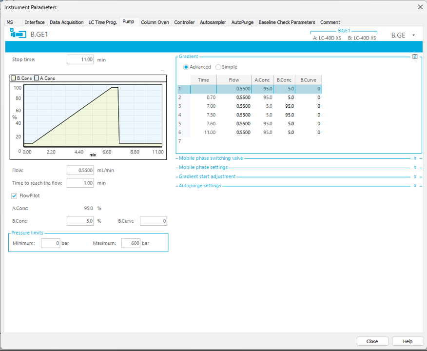
Fig. 2 Check the LCMS method settings to ensure all conditions are correctly set |
| Air in System or Pump Malfunction | Air bubbles or pump malfunctioning can interrupt the solvent delivery which in turn will affect elution or detection of the peak |
Purge both pumps and injector thoroughly
Run an IPA purge to test and clean the check valves
Ensure pump performance is stable and pressure trace is smooth
|
| Blocked or Damaged Tubing | Crimped or blocked tubing restricts flow and may stop analyte delivery to the detector |
Inspect and replace any damaged or crimped tubing
Observe system pressure for irregular increases indicating restriction
|
| Incorrect Retention or Elution | Compounds may elute in the void volume (too early) or remain retained on the column (not eluting) |
Review mobile phase composition and gradient
Ensure the correct analytical column is installed
Increase run time or gradient strength to achieve elution
|
| Incorrect Flow Rate | Flow rate errors may prevent analyte transfer to the MS or reduce sensitivity |
Verify flow rate against method requirements
Adjust as necessary to match validated conditions
|
| Blocked Injection Needle | A blocked injection needle prevents sample introduction to the system, often with increased pressure |
Attempt needle rinse or cleaning procedures
|
| Divert Valve or Waste Routing | The analyte may be diverted to waste by a programmed time event |
Check divert valve settings and time programs
Ensure the valve directs flow to the MS during the expected elution window

Fig. 3 Valve program set to waste after 2.000 mins |
The above examples should provide the most observed issues which might cause the peak to be unobserved. By systematically ruling out either the MS, LC or sample, focus can be directed to the mostly likely culprit which can then get you back up and running again once fixed.
In the next course unit, we will look into changes in peak shape and their most common causes.
Your Shimadzu LCMS team
Next week's units will be delivered directly to your inbox according to your weekly schedule, but if you can't wait and would prefer to continue with the course now, click here.
Related Resources
-
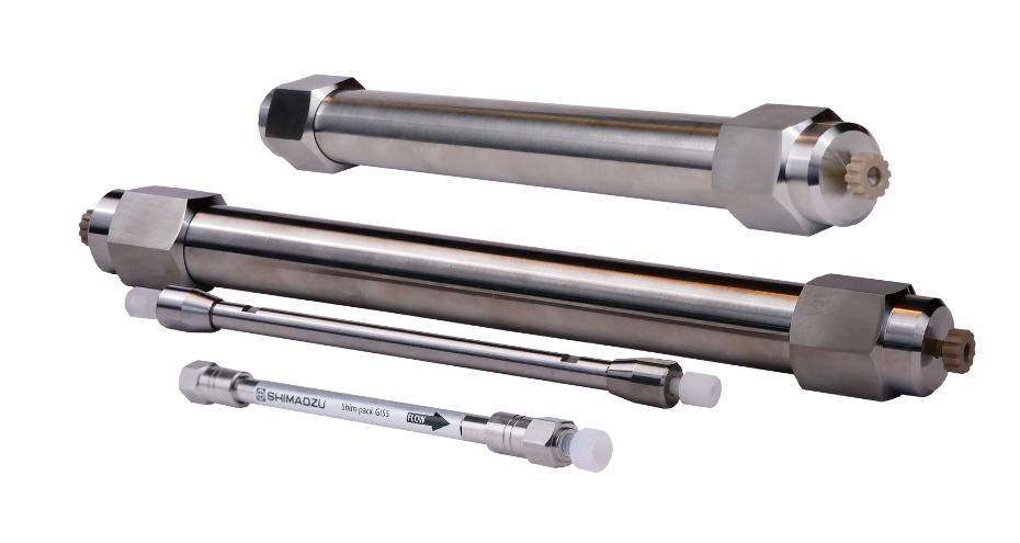
Search Shimadzu's range of HPLC columns to find the right one for your application.
-
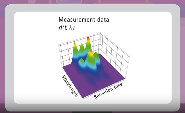
Watch short videos explaining analytical intelligence features of Shimadzu HPLC systems
-

Learn about our beginnings, dating back to 1875, through to modern day Shimadzu.