Changes in Peak Shape (Part 2)
LCMS Troubleshooting Course
6 - Changes in Peak Shape - Part 2
7 - Ghost Peaks
8 - Peak Area Fluctuations
9 - Baseline Disturbances
10 - Retention Time Fluctuations - Part 1
11 - Retention Time Fluctuations - Part 2
12 - Changes in Chromatographic Resolution
13 - Changes in MS Response
14 - Undesired Fragmentation & Ion Source Settings
15 - Course Summary & Quiz
Part 2: Causes of Peak Shape Changes in LCMS
This topic is divided into two parts:
- 1. Injection & data acquisition effects on peak shape.
- 2. Causes of peak shape changes (fronting, tailing, broadening) and MS-specific factors.
In the last course unit, we began to look at some of the causes of peak shape changes, which can impact on the accuracy and reliability of our data.This week, we shall look at specific peak shape issues and their causes.
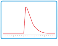
A: Peak Fronting

This is characterised by a steep peak rise and shallow tail, known as a "shark fin"
| Issue | Description | Solution |
|---|---|---|
| Column Damage | The column is a consumable with a lifespan. The column could just be aging, or potentially the lifespan could be reduced if working outside the manufacturer's specifications (i.e. pH or temperature range) |
Replace the aging columns
Adhere to column specifications to prolong the lifetime of the columns
|
| Sample Overloading | Overloading can be caused by excess analyte saturating the column or overwhelming the ionisation capacity, thereby distorting the peaks. |
Reduce the sample load or use a column with a larger ID
Decrease the concentration of the sample
|
| Sample Solvent Incompatibility or Poor Solubility | The sample diluent is integral to the peak shape. If the sample solvent is too strong, it can cause the analyte band to spread and distort. |
Assess the applicability of more compatible solvents
If the sample solvent cannot be changed, use a sandwich injection, which can be programmed by the software to aspirate a volume of water prior to the sample, then a final volume of water to compact the band. This is particularly beneficial for early eluters.
|
| MS Specific Considerations | If the sample is too concentrated, the MS signal can max out where the detector is saturation, causing flat topped peaks. |
Reduce the injection volume or decrease the sample concentration by diluting the sample
Use "high" quadrupole resolution in MRM to reduce peak distortion from overlapping transitions
|
B: Peak Tailing
This is observed as the opposite of a fronted peak, where there is a slow descent of the peak which is typically observed for basic species. If this behaviour is observed in neutral species, it would indicate issues with the column.
| Issues | Description | Solution |
|---|---|---|
| Secondary Interactions | Secondary interactions between a charged analyte and a charged moiety on the stationary phase, such as residual silanol groups, can cause the peak to present a broad tail. |
If possible, work with the analyte in the unionised form (i.e. for basic species, use a pH above the pKa of the analyte, or for acidic species, use a pH below the pKa of the analyte). Beware of any column limitations.
Use a column with reduced acidic silanols and low metal content. Adhere to column specifications to prolong the lifetime of the columns
Change column type
|
| Inadequate Buffering | Ionisable species require adequate buffering in order to maintain suitable peak shape. Be aware that 0.1% formic acid only equates to ~2 mM which in some circumstances is not sufficient. |
Increase buffer concentration up to 10 mM to increase buffering capacity
|
| Column Damage | If the column is damaged or the integrity of the packed bed is impacted, the shape of all peaks could be impacted. |
Replace the column
Adhere to column specifications to prolong the lifetime of the columns
|
| Adsorption | Adsorption of the analyte in tubing or fittings can cause tailing. Another common problem is chelation of the analyte with metals in the wettable flow path. |
Passivate the system or use a bioinert system to remove metals from the flowpath
Use an ion pair to limit interactions with the active sites. Remember to dedicate that column to be used only with that ion pair due to memory effects.
Change the column to a PEEK format or use a bioinert column
|
| Sample Loading | As previously discussed, the sample concentration can cause an increase in peak tailing, which is due to the adsorption Langmuir Isotherm. |
Reduce sample concentration by injecting less or dilution
|
| Interfering Peak | If there are two peaks which possess the same transitions, such as regioisomeric species, it might be possible that the two species are not adequately resolved, thereby causing a peak to appear tailed. |
Use a longer column to increase the resolving power
Change gradient conditions
Further method development to resolve the interfering peak from the peak of interest
Change the column phase type
|
| Column Voiding or Degradation | If the integrity of the column has |
Replace the column
|
| Dead Volume | If the column has not been installed correctly, it can create additional volume at the head of the column, which can cause peak issues. |
Reconnect the column with the fitting to reduce the dead volume
|
| MS Specific Causes | Poor ionisation or source contamination can worsen tailing by stretching ion arrival times. |
Clean the source and verify spray stability
|
C: Peak Broadening
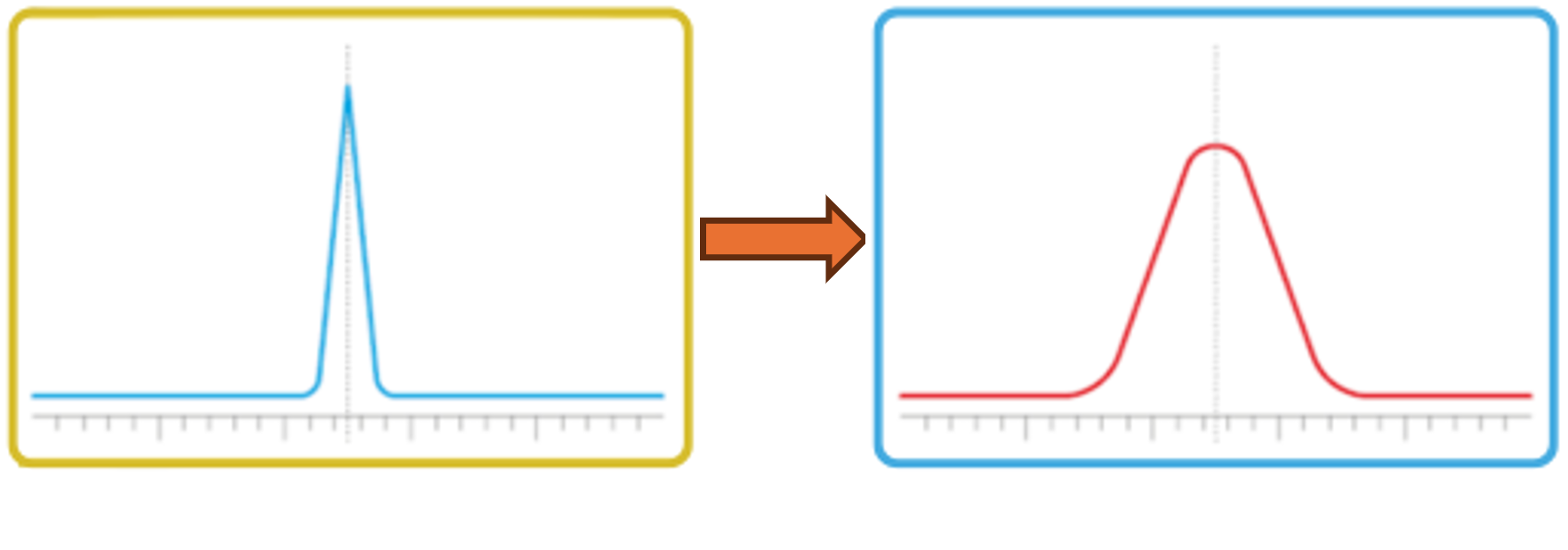
Peak naturally spread throughout the chromatographic system, which is why they produce their characteristic peak shape. However, we want these peaks to be as narrow as possible, which means we need to optimise the system to minimise system volume and dispersion. It is also important to notice if peak shapes change over the course of several analyses because this can impact on your resolution.
| Issue | Description | Solution |
|---|---|---|
| Dead Volume | An incorrectly installed column could cause band broadening, presenting as a broader peak |
Reseat the fittings to minimise any dispersive effects.
Change any wide ID tubing to minimise system volume (pressure permitting)
|
| Detector Response Time Too High | The detector settings could be set that it is artificially increasing the width of the peak. |
Assess different response settings and observe if there is an improvement in results
|
| Column Aging | As a consumable, the column can age causing performance to deteriorate. This can result in peaks broadening. |
Replace the column
|
| Longitudinal Diffusion in Isocratic Runs | Peak broadening due to residency time in the column is just a characteristic of isocratic runs. The longer the analyte is on the column, the broader it will be. |
Assess if gradient conditions can be used in place of the isocratic conditions.
Alternatively, look to bring the peaks off earlier in isocratic mode by increasing organic composition or increasing column temperature within column specifications.
|
| Sample Loading | See previous comments. |
Reduce the sample concentration or decrease the injection volume
Reduce the % organic concentration in the sample diluent
|
| Oven Setting Issues | If the wrong settings have been used on the oven compared to the original method, peaks might change peak width. |
Check the column oven temperature is correctly set in the method.
Higher column temperatures typically result in faster compound elution, however, the conditions should be appropriate for both the column specification and analyte to prevent degradation.
|
| Mobile Phase | The wrong mobile phase will give a wrong response which could include changes in peak shape as well as changes in retention time. |
Check the correct mobile composition is being used in the method.
Reprepare the mobile phase if in doubt
|
| Slipped Ferrule | A slipped ferrule could result in poor connections which causes peak dispersion. |
Check all connections are correctly fitted
|
| LC Setup | The LC setup should be recorded to ensure that the same dwell volume and system volume is used for all analyses. The dwell volume is the tubing between where the two solvents meet, typically at the mixer in high pressure mixing systems or the proportionating valve in low pressure mixing systems, to the head of the column. The system volume is the volume from the point of injection through to the head of the column. Changes in these values can change peak width |
Check tubing lengths, the mixer volume, vlave / column connections and internal dimensions.
Check the correct flow rate is being delivered / set in the method.
|
| MS Specific Causes | Ion suppression and spray instability can cause changes in peak width. Erratic nebuliser gas or probe positioning widens the peak response times, therefore notes should be taken to ensure the probe is positioned correctly and the spray should be investigated for stability. |
Coeluting matrix components can reduce analyte response, visually flattening peaks, therefore efforts should be made to reduce ion suppression by method development to move the peak of interest from the matrix
Inspect spray and tune ion source with a probe distance ~2-3 mm, and capillary protrusion typically 0.5-1 mm.
Optimise the gas flows and temperatures of the ion source.
Use sample cleanup (e.g. SPE, protein precipitation) to reduce matrix effects
|
D: Peak Splitting
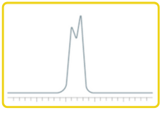
This is characterised by two peak apexes instead of a single peak for one compound.
| Issue | Description | Solution |
|---|---|---|
| Soiled Guard or Column Inlet | This is commonly from insufficient sample preparation. |
Replace the aging columns
Adhere to column specifications to prolong the lifetime of the columns
|
| Sample Diluent Incompatibility with Mobile Phase | The sample diluent can be too strong, and particularly for early eluters, can negatively impact peak shape, often with split peaks. |
Change the sample diluent, ideally using the initial mobile phase solvent composition if appropriate
Use the cosolvent sandwich injection to create a compact band at the head of the column
|
| Analyte Properties | The properties of the compound could cause peak splitting, such as isomers or analyte interconversion |
Assess different analytical conditions to correct for this.
|
| Detector Saturation | The peak shape could be negatively impacted by the detector being saturated with samples, which should be investigated and rectified. |
Reduce injection volume or inject lower concentration of the sample
Set quadrupoles to "high" resolution for anaytes affected in MRM method
|
Additonal LCMS Troubleshooting for Peak Shape Issues
If peaks are missing, split, or distorted despite proper LC conditions:
Daily LCMS Peak Shape Checklist
In this second course unit of the changes in peak shape, the possible causes for various effects are explained. The most common cases people see in practice are tailing and peak broadening. It is imperative to improve the peak shapes we observe in order to maximise on resolution between peaks of interest and ensure impurities are not hiding underneath a peak.
In the next course unit, we will be looking at ghost peaks and contamination.
Your Shimadzu LCMS Team
Next week's units will be delivered directly to your inbox according to your weekly schedule, but if you can't wait and would prefer to continue with the course now, click here.
Related Resources
-
-
Watch short videos explaining analytical intelligence features of Shimadzu HPLC systems
-